Week Five Update
Insertion of Working Fluid
This week, the group finished the first heat pipe prototype to be tested in lab. It contains roughly 30mL of distilled water as a working fluid and a sponge interior as a wick, but does not yet have a radiator. It was decided that the pipe should be tested without the radiator first so that the effects of the extra heat fins can be measured and used for calculations to determine the optimal shape, orientation, and amount of radiator fins. The amount of working fluid and type of wick are also likely to be modified after testing. This is the first working model, so future changes are expected.
 |
| Figure 1: Pouring boiled distilled water into the pipe |
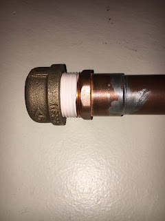
Filling the heat pipe with working fluid is more complex than it initially sounds. To avoid excess pressure build-up, the material of the pipe, wick, and working fluid most all be non-reactive. Additionally, the amount of working fluid must be carefully determined and inserted correctly so that the heat pipe does not explode while it is heated. To accomplish this, distilled water is boiled before it is poured into the heat pipe. The boiling water produces steam which pushes excess oxygen out of the pipe. The pipe is sealed using a threaded cap with polytetrafluoroethylene tape to lubricate and seal the threads. Because the pipe is sealed while gaseous water is present to evacuate air from the pipe, when it cools, the pipe will have a pressure below 1 atm. This low pressure within the pipe will lower the boiling point of the working fluid. A lower boiling point is ideal in this situation because it allows for easier vaporization of the working fluid during pipe operation which increases heat transfer efficiency. It is also ideal because when the distilled water boils, it will not increase the pressure of the pipe above atmospheric pressure. This minimizes risks of leaks developing or catastrophic failure in the form of a pipe rupture.
 |
| Figure 2: This shows the sealed pipe with threaded cap and polytetrafluoroethylene tape. |
Leak Discovery and Repair Plan
During week five lab, a leak was discovered in the seal between the bronze cap and the copper pipe. Liquid water was able to seep through the seal which also means that the pipe is not air-tight. This is concerning because it means that the inside of the pipe is now at 1 atm of pressure. If the pipe is resealed and then heated, the internal pressure of the pipe will rise above 1 atm of pressure and present a risk of explosion. Further research will be conducted to determine how much pressure the pipe will be able to handle before it fails.
To fix the seal, it will be necessary to remove the cap, apply another layer of polytetrafluoroethylene tape, and then use a large wrench to tighten the cap as much as possible rather than tightening it by hand. Such a wrench will need to be acquired somehow.
Calculating Maximum Internal Pressure
First Test
In class for week 5. The heat pipe went through its first test. The set up was as followed.
 |
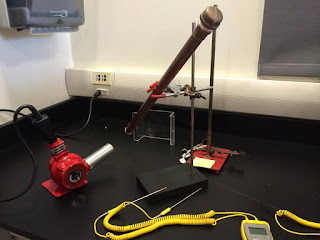
| Figure 3: The set up for the first test |
The pipe was put in a diagonal position with one head close to the heat gun while the other head away from the heat gun. There was three heat sensors that was attached to the pipe. One at each end and one in the middle. The purpose of these sensors were to keep track of the temperature change and to see if the pipe was transferring heat and if so, how effectively? The following were the temperature at the initially for the pipe.
 |
| Figure 4. Temperature at the condenser end initially |
 |
| Figure 5. Temperature at the middle of the pipe initially |
The following are the time of the pipe after the heat was applied constantly for 8 and a half minutes.
 |
| Figure 6. Temperature at the condenser end after 8.5 minutes |
 |
| Figure 7. Temperature at the middle of the pipe after 8.5 minutes |
First Test Results
The lack of consistency in the evaporator end curve is due to the fact that the thermal probe was held by a person rather than by tape. The tape would have melted at those temperatures. The fact that the middle temperature probe begins to decline is probably due to the fact that the tape loosened due to the heat and caused the probe to shift.
In future tests, these issues will be considered so that more accurate test results can be acquired. Additionally, variables such as removing the wick and introducing radiator fins to the condenser end will be introduced.

This comment has been removed by the author.
ReplyDeleteThe problem might be the amount of fluid in the pipe. Please discuss with Prof. Speidel about whether you should increase the fluid volume.
ReplyDelete