Navigation

Drop Down MenusCSS Drop Down MenuPure CSS Dropdown Menu

Wednesday, April 27, 2016

Week Five Update

Week Five Update

Insertion of Working Fluid

This week, the group finished the first heat pipe prototype to be tested in lab. It contains roughly 30mL of distilled water as a working fluid and a sponge interior as a wick, but does not yet have a radiator. It was decided that the pipe should be tested without the radiator first so that the effects of the extra heat fins can be measured and used for calculations to determine the optimal shape, orientation, and amount of radiator fins. The amount of working fluid and type of wick are also likely to be modified after testing. This is the first working model, so future changes are expected.


Figure 1: Pouring boiled distilled water into the pipe


Filling the heat pipe with working fluid is more complex than it initially sounds. To avoid excess pressure build-up, the material of the pipe, wick, and working fluid most all be non-reactive. Additionally, the amount of working fluid must be carefully determined and inserted correctly so that the heat pipe does not explode while it is heated. To accomplish this, distilled water is boiled before it is poured into the heat pipe. The boiling water produces steam which pushes excess oxygen out of the pipe. The pipe is sealed using a threaded cap with polytetrafluoroethylene tape to lubricate and seal the threads. Because the pipe is sealed while gaseous water is present to evacuate air from the pipe, when it cools, the pipe will have a pressure below 1 atm. This low pressure within the pipe will lower the boiling point of the working fluid. A lower boiling point is ideal in this situation because it allows for easier vaporization of the working fluid during pipe operation which increases heat transfer efficiency. It is also ideal because when the distilled water boils, it will not increase the pressure of the pipe above atmospheric pressure. This minimizes risks of leaks developing or catastrophic failure in the form of a pipe rupture.
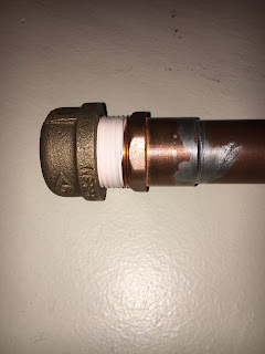
Figure 2: This shows the sealed pipe with threaded cap and polytetrafluoroethylene tape. 

Leak Discovery and Repair Plan

During week five lab, a leak was discovered in the seal between the bronze cap and the copper pipe. Liquid water was able to seep through the seal which also means that the pipe is not air-tight. This is concerning because it means that the inside of the pipe is now at 1 atm of pressure. If the pipe is resealed and then heated, the internal pressure of the pipe will rise above 1 atm of pressure and present a risk of explosion. Further research will be conducted to determine how much pressure the pipe will be able to handle before it fails.
To fix the seal, it will be necessary to remove the cap, apply another layer of polytetrafluoroethylene tape, and then use a large wrench to tighten the cap as much as possible rather than tightening it by hand. Such a wrench will need to be acquired somehow. 

Calculating Maximum Internal Pressure

One key factor of the heat pipe is to ensure that is safe, and that includes ensuring that the pipe does not burst while testing. The equation as seen shows how much pressure can be on the pipe before it bursts, that value is calculated from known values such as maximum tensile stress of copper, and dimensions of the pipe. From those values we got a maximum allowable pressure of 177 atm.


First Test

In class for week 5. The heat pipe went through its first test. The set up was as followed.
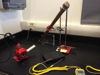

Figure 3: The set up for the first test

The pipe was put in a diagonal position with one head close to the heat gun while the other head away from the heat gun. There was three heat sensors that was attached to the pipe. One at each end and one in the middle. The purpose of these sensors were to keep track of the temperature change and to see if the pipe was transferring heat and if so, how effectively? The following were the temperature at the initially for the pipe.

Figure 4. Temperature at the condenser end initially

Figure 5. Temperature at the middle of the pipe initially


The following are the time of the pipe after the heat was applied constantly for 8 and a half minutes.
Figure 6. Temperature at the condenser end after 8.5 minutes

Figure 7. Temperature at the middle of the pipe after 8.5 minutes
As seen from above, the condenser end went initially from 78°F to only 86°F after 8 minutes. This shows that the heat pipe did work but to a very minimal extent. This is the test with the wick inside of the pipe. The pipe will have to be tested a few more time with modifications to decide which design is best for the pipe.

First Test Results


The lack of consistency in the evaporator end curve is due to the fact that the thermal probe was held by a person rather than by tape. The tape would have melted at those temperatures. The fact that the middle temperature probe begins to decline is probably due to the fact that the tape loosened due to the heat and caused the probe to shift. 
In future tests, these issues will be considered so that more accurate test results can be acquired. Additionally, variables such as removing the wick and introducing radiator fins to the condenser end will be introduced.


Thursday, April 21, 2016

Week Four Update

Week Four Update

Construction of the heat pipe is almost complete. During this week, calculations were done to determine how much heat the pipe will transfer and the caps of the pipe were soldered. 

Heat Transfer Calculations

The page displayed below shows the calculations that describe heat transferred through the copper walls of the pipe due to conduction. This value was determined to be only 26.55 J which makes sense considering the small cross sectional area of copper and the relatively long length of pipe. The "Hot" temperature was assumed to be the maximum temperature of 533 degrees Kelvin. The "Cold" temperature was assumed to be 294 degrees Kelvin (room temperature). 

The page below displays calculations of heat transfer due to the phase transition of the working fluid. This is the essential method of heat transfer in the pipe and transfers the majority of the thermal energy that is input into the pipe. These calculations are broken down into two parts: heating liquid water to its boiling point, and vaporizing the water. Heating water vapor can be ignored since the water vapor travels to the condenser end of the pipe as soon as it vaporizes. Therefore, the vapor itself does not gain much thermal energy. The amount of energy transferred in the phase transitions of the working fluid is roughly 84 kJ. This value is much higher than the amount of heat transferred through the copper. This great different is expected. It demonstrates the working principle of heat pipes and provides a quantitative understanding of how efficient heat pipes are when compared to solid metal rods. Proportionally, the heat transferred through the copper is almost negligible when added with the heat transferred in the phase transitions of the working fluid. The total heat transferred is roughly 84 kJ.


To quantify the difference in heat transfer between the heat pipe and a solid copper rod of the same dimensions, the amount of heat that would be transferred through a solid copper rod was calculated. This is very similar to the calculation on the first page, however, the cross sectional area of the copper is much larger because it is a solid rod rather than a hollow pipe. A solid copper rod of the same dimensions as the heat pipe transfers 106.65 J of heat. When compared with the heat transferred through the heat pipe (84 kJ) it is determined that the heat pipe design is 200% more efficient at transferring heat than a solid copper rod of the same dimensions. This clearly shows the advantages of heat pipes in heat transfer applications. 


Soldering

The pipe and end caps were brought to the machine shop for soldering. The ends of the pipe and insides of the caps were cleaned with scotch brite and methanol. A machine shop technician performed the soldering with plumbing solder.


Saturday, April 16, 2016

Week Three Update

Week Three Update

Construction of the heat pipe began in week three. One of the major components of the device, the wick, was assembled and placed inside of the pipe. The two sealing caps were fitted to the pipe, but they will not be soldered until next week.

Wick Construction

In any horizontal heat pipe, a wick is necessary to transport working fluid from the condenser end to the evaporator end through capillary motion. To complete this task, the wick must be made of a material that allows for liquid flow due to capillary motion. Certain industrial heat pipes have shaped wicks with thin channels that allow for this, however, for the first prototype, the design will use a simple sponge lining. Further testing with various wicks will be conducted to determine the most effective material and shape. 
To assemble the wick, several sponges were sliced into thin layers. These layers were then glued to a piece of coated, water resistant paper. This paper was then rolled into a cylinder with the sponges facing inward. This cylinder was inserted into the end of the heat pipe and wooden spacers were inserted to better mold the sponges to the curved shape of the pipe over the course of the week. 


Planning Ahead


The next major component that need to be added to the heat pipe will be the radiators. Originally, the radiator was thought to be able to put onto the pipe by simply soldering or welding it. However, in order for the radiators to work well, it has to be a metal to metal contact between the radiator and the pipe body. Another potential problem in applying the radiator is the spacing between the different fins of the radiators. Since the work space is around a 1 inch diameter pipe, it will be quite small to be able to evenly space out the fins. To deal with this problem, by aligning the fins up first and attach it to a flat sheet of metal, then bending the sheet of metal around the tube, it will deal with the problem of working around the pipe to attach each individual fin. This is easier said than done but currently this is the plan for attaching the radiator.


In order to see the effectiveness of the pipe. The pipe will be tested first without the radiators and then once again with the radiator. If the non-radiator pipe works better than the radiator pipe then the radiator will need to be reworked.


Thursday, April 7, 2016

Week Two Update

Week Two Update

The major tasks of this week include the construction of a CAD model, virtual testing of this CAD model, design proposal completion, and material acquisition.

CAD Model

A computer aided design model was completed to provide a "blueprint" for manufacturing and to provide a model for computer aided thermal testing. The figures below display this model.


The pipe design is 2' in length and is 1" in diameter. The condenser end of the pipe has 40 radiator fins protruding radially from the pipe. Both ends of the pipe have 1" diameter caps to seal the pipe. In addition to this, there is a shaped wick design that lines the interior of the pipe. This wick design is displayed below (figure displays end of pipe with cap removed).

Computer Aided Testing

Creating a three dimensional CAD model also enables thermal testing to be conducted. In the test displayed below, a thermal stress of  200 degrees Celsius was applied to the evaporator end of the heat pipe design. This test simulates the effects of heat conduction through the walls of the copper pipe and heat loss due to convection. Autodesk Fusion 360 is unable to simulate heat transfer due to the phase transition of the working fluid, however, this simulation still provides an understanding of how much heat is dissipated by the materials of the pipe itself. It will provide a better idea of the amount of heat transferred by the two mechanisms in the heat pipe: conduction through the copper in the pipe and heat transfer due to the phase transition of the working fluid.


Material Acquisition

This week the group went to get the initial materials for the heat pipe prototype. The material that the pipe is made of is copper, and the cap for the pipe is also copper. One end of the pipe will have a threaded end soldered on, and will be closed with a threaded bronze cap. The wick material has not been acquired, but we decided on getting cotton pads to line the pipe. Finding an adhesive that can withstand high temperatures also proved to be difficult. The total cost of materials for the pipe thus far is approximately $50. 


Design Proposal Completion

A design proposal was written, with each team member contributing to various sections. In the proposal, various aspects of the project were detailed. The paper outlines the deliverable heat pipe to be constructed, and discusses the design and properties of it, as well as the research behind the selected design. A timeline was proposed, outlining what weeks of the project will correspond with different stages, such as research, materials acquisition, manufacturing, testing, and optimization. Different skills, tools, and work spaces required for the completion of the project were listed, as well as a budget for all of the materials necessary.

Monday, April 4, 2016

Background/Tutorial/FAQ

FAQs

1) How do heat pipes work?

2) What are some  applications for heat pipes?

CPU heat management, Wankel engine cooling, spacecraft heat management, permafrost cooling, cooking, and ventilation heat recovery.

3) Are there any dangers?

Heat pipes are sealed containers with fluid inside. If they are designed improperly there is a risk of explosion when gasses expand from heating. Additionally, depending on the working temperature range, heat pipes may become dangerously hot and present a burn or fire danger.

4) Are they in high demand?

Heat pipes are used in many modern technological applications. They are necessary in many applications that require the transfer of thermal energy from one point to another.

5) How reliable are they?

Once built, heat pipes are extremely reliable and require little to no maintenance. This makes them especially useful in applications where maintenance is difficult to perform such as on a spacecraft heat control system.


References:

[1]  C. E. Heuer, “The Application of Heat Pipes on the Trans-Alaska Pipeline,” U.S. Army Corps of Engineers, Hanover, NH, Special Report 79-26, 1979.
[4]  G. M. Grover, “Evaporation-condensation heat transfer device,” U.S. Patent 3 229 759, Jan. 18, 1966.


Biographies

Biographies

Michael Buss (mjb522@drexel.edu)


Michael is a freshman mechanical engineering student at Drexel university. He has always been interested in science and engineering and can often be found tinkering with old electronics and machines and building new ones in his free time. Michael aspires to earn a graduate degree in aerospace engineering after he graduates from Drexel. 


Nhat Duong (nd458@drexel.edu)

Nhat Duong is a student at the College of Biomedical Engineering of Drexel University. He is from Allentown PA. Other than Biomedical Engineering, he is also interested in learning about any other field of engineering. He likes to learn about anything that he did not know about and get easily amused by random facts. By participating in the heat pipe project, he intended to learn more about how heat pipes work and the different applications for heat pipes. Outside of school, he usually finds himself dancing and listening to music to relax. His goal one day is to be able to help better people’s life and be part of a great medical breakthrough.


Austin Omolo (aro42@drexel.edu)

Mr. Austin Omolo is a rising freshman currently pursuing a degree in Chemical Engineering. Aside from Chemical Engineering being the toughest major around (he tends to like a challenge), he chose this major because he is passionate about the environment. Austin intends to pursue a PhD and conduct research on green energy. This is because he believes the environment is often compromised in pursuit for energy, and that the two can be married in the form of green energy!


Eric Tran (evt25@drexel.edu)

Eric is studying biomedical engineering at Drexel University. He has been interested in all the aspects of STEM education early on, and with biomedical engineering he feels that it has a wide range of study for him to be exposed to. He chose this project with heat pipes for the same reason, it may not directly translate to something in his career, just the exposure to a different part of engineering is valuable experience for him.


Alex Humen (aah99@drexel.edu)

Alex Human is a Biomedical Engineering major from Kensington, Connecticut. He plans to major in biomechanics, and hopes to work in research and development, particularly in prosthetic technology